 Skip to content
High Precision Robotic Actuator
Python | Mechanical Design| Solidworks | Ansys | MATLAB | DFMA
Project Overview
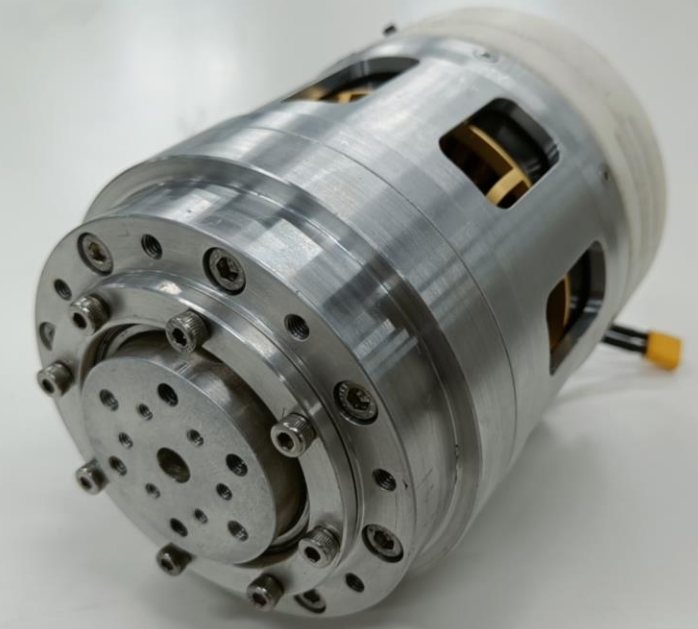
During my final semester of undergraduate studies in Mechanical Engineering at Manipal Institute of Technology, I interned for 6-months at Twara Robotics (formerly Gati Robotics). Under the supervision of Dr. Kaushik Sampath, CEO and Founder, I designed a thermoplastics-based strain wave gearbox for a smart Robotic Actuator.
Twara Robotics, incubated at ARTPARK (AI & Robotics Technology Park), IISc Bangalore, aims to design and manufacture components like Robotic Actuators and Soft Grippers in India. The company aims to be a leading manufacturer of high-precision, high-torque integrated actuators, featuring indigenously developed motor drivers, brushless DC motors, brakes, and gearboxes.
Strain wave gearing, also known as the harmonic drive, is a unique type of mechanical gear system that leverages a flexible spline with external teeth, which is deformed by a rotating elliptical cam to engage with the internal gear teeth of an outer spline. This innovative design offers several advantages over traditional gearing systems, including zero backlash, compactness, high gear ratios, excellent repeatability, high torque capability, and coaxial input and output shafts. By harnessing the flexibility of the spline and the elliptical motion of the cam, strain wave gearing achieves high gear reduction ratios in a small volume, making it the perfect solution for applications requiring precise and efficient power transmission.
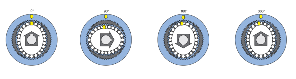
The strain wave gearing mechanism is composed of three components – a circular spline (blue), a flex spline (red) and a wave generator (green), as shown in the animation above. The mechanism leverages the elasticity of the flex spline to obtain large reduction ratios in a compact form factor. The teeth on the flexible flex spline mesh with the teeth on the rigid circular spline and a continuously propagating wave-like input is provided by the elliptically shaped wave generator.
The flexspline is slightly smaller in diameter and has two fewer teeth than the circular spline. The elliptical shape of the wave generator causes the teeth of the flexspline to engage the circular spline at two opposite regions across the major axis of the ellipse. For every 180-degree clockwise rotation of the wave generator, the flexspline teeth are advanced counterclockwise by one tooth in relation to the circular spline. The figure below illustrates how one complete clockwise rotation of the wave generator, results in the flexspline moving counter-clockwise by two teeth from its original position. Because the gear teeth are always fully engaged in a region along the major axis, strain wave gear reducers have zero backlash.
The goal of the internship was to develop a novel design for a compact, lightweight, low backlash, and high torque density strain wave gear reducer made from thermoplastics using additive manufacturing techniques. Custom Testing rigs were used to benchmark the actuators to determine static load-bearing capability, positional accuracy, repeatability, backlash error and efficiency. A set of primary design parameters were identified to fine-tune the functioning of the actuator. The design of the following components drives the performance characteristics of the gearbox:
- Gear teeth profile
- Wave generator profile
- Bearing characteristics
- Design of the flexible spline
- Design of the circular spline
- Structural design of the gearbox assembly
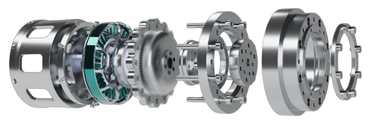
The goal of the design and testing process was to converge upon an optimal solution based on performance specifications, with the design of the aforementioned components serving as input variables. The figure below details the latest design of the actuator.
Gearbox Specifications:
- Dimensions – Outer Diameter = 100 mm, Length = 150 mm
- Weight – 2.5 kgs
- Loading Specifications:
(a) Maximum / Breaking torque – 75 Nm
(b) Nominal / Rated torque – 20 Nm
(c) Maximum dynamic axial & radial load – 10 KN - Maximum permissible backlash – 15 arc-seconds
- Number of cycles to be sustained at rated torque – 100,000
- Efficiency – 50%
A link to download the full “Robotic Actuator Specification Datasheet” can be found here.
The test setup for the gearbox comprises of three stages. First is predictive testing, which makes use of computer simulations to evaluate designs before they are fabricated. This is followed by physical testing which consists of a comprehensive set of controlled tests that characterize the performance of the fabricated prototypes. Finally, the test data is analysed and the findings are used to drive subsequent designs.
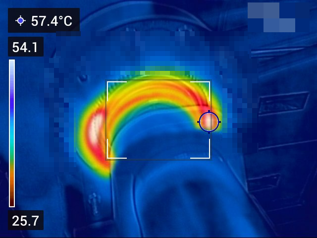
A thermal camera is used to study the heat generated at the circular-spline and flexible-spline interface and the wave generator and flexible-spline interface. The gears that are manufactured using thermoplastic polymer materials are highly susceptible to plastic deformation at elevated temperatures when subjected to loading. The figure below is the output image obtained from the thermal camera. This image is used to characterize the thermal performance of the gearbox.
A magnetic hysteresis brake is a valuable tool for motor/gearbox testing, allowing for controlled loading, speed control, torque measurement, overload protection, and dynamic testing. By applying a precisely controlled magnetic field, the brake can simulate real-world operating conditions, enabling the evaluation of performance, efficiency, reliability, durability, and quality control. A test rig with a hysteresis brake was used to benchmark the performance of various actuator prototypes.
This work led to the filing of a Patent Application – Flexible Spline and Wave Generator for Strain Wave Gearing. Application Number: 202341066798, India.
