 Skip to content
Robot Light Painter
ROS2 | C++ | Python | Computer Vision | OpenCV | Kinematics | Navigation | Path Planning
Project Overview
For my winter project at Northwestern University’s Masters in Robotics program, I used a TurtleBot3 robot to create Light Paintings. Waypoint data extracted from images is used to plan the path of the TurtleBot. Continuous feedback from the OptiTrack Motion Capture system is used to correct the position of the robot in real time as it drives around the environment. An LED matrix atop the robot displays the color to be used in the painting. A Computer Vision program tracks the color in the video feed and creates a Light Painting as the robot traces the path of the drawing.
Light Painting using a TurtleBot3
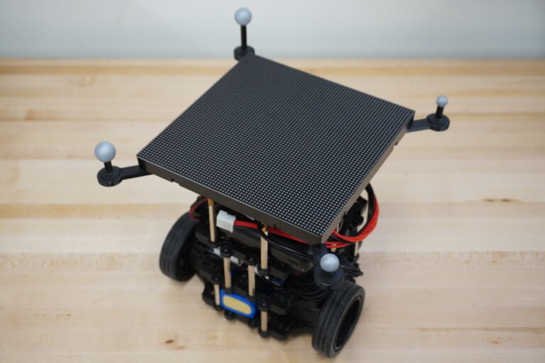
Hardware Description
The 2D Lidar on a standard TurtleBot3 Burger robot is replaced by a 64×64 RGB LED Matrix from Adafruit. The LED matrix is controlled using a Raspberry Pi and an Adafruit RGB Matrix Bonnet. Four retroreflective markers are placed around the LED matrix. These markers are used by the Motion Capture system to localize the robot inside the capture volume.
The SVG image is converted to GCode using the svg2gcode library. A python program is used to parse the GCode file and extract the relevant waypoint data for the Turtlebot. These waypoints are used by the path planner to construct a navigation routine which creates the Light Painting.
The OptiTrack Motion Capture system facilitates accurate, low-latency six degrees of freedom (6 DoF) tracking of the TurtleBot’s movements as it navigates through its environment. The TurtleBot is susceptible to positional drift over time, particularly when relying solely on wheel encoder feedback (wheel odometry) for open-loop control. Integration of Motion Capture data greatly enhances the effectiveness of the motion planner. By leveraging this data, the planner can more reliably guide the robot along desired trajectories, for extended durations of time, without accumulating significant positional errors.
OptiTrack Motion Capture Visualization
Before attempting to draw, the computer vision program must be calibrated to track a specific color in the scene. A calibration routine is executed, which allows the user to modify HSV values in an image to create an image mask. This mask is applied over the video feed to isolate the color of the light painting.
Color Tracking Calibration
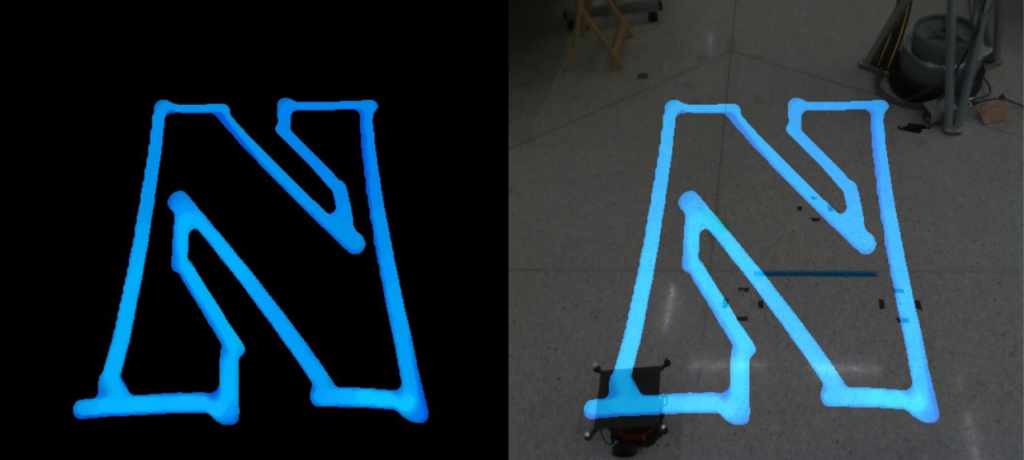
The video below shows a light painting being created from scratch. A RealSense RGB camera is used to capture a video feed that is processed in real time to construct the drawing. The four windows in the video are:
- Top Left – Original Video
- Top Right – Tracked Color
- Bottom Left – Light Painting
- Bottom Right – Overlay of the Video with the Light Painting
Light Painting Example
